Download Arduino IDE
– untar and run install.sh
– run IDE and install the ESP32 Board
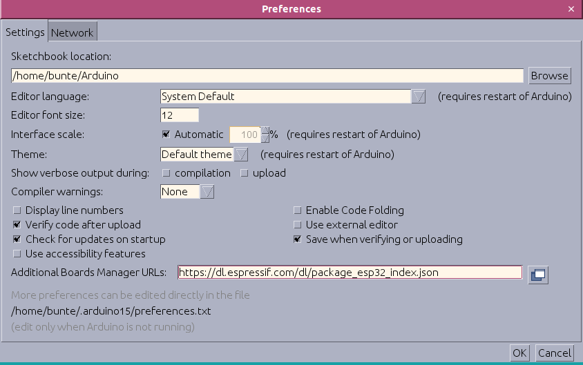
In your Arduino IDE, go to File> Preferences
Enter https://dl.espressif.com/dl/package_esp32_index.json into the “Additional Board Manager URLs” field as shown in the figure below. Then, click the “OK” button.
If other Boards are present you can seperate list with comma:
https://dl.espressif.com/dl/package_esp32_index.json, http://arduino.esp8266.com/stable/package_esp8266com_index.json
Open the Boards Manager. Go to Tools > Board > Boards Manager
Search for ESP32 and press install button for the ESP32 by Espressif Systems.
Plug the ESP32 board to your computer. With your Arduino IDE open, follow these steps.
tail -f /var/log/syslog
Nov 11 10:35:29 OlisUbuntu kernel: [ 5741.868594] usbserial: USB Serial support registered for cp210x
Nov 11 10:35:29 OlisUbuntu kernel: [ 5741.868630] cp210x 1-7.1:1.0: cp210x converter detected
Nov 11 10:35:29 OlisUbuntu kernel: [ 5741.869034] usb 1-7.1: cp210x converter now attached to ttyUSB0
1. Select your Board in Tools > Board menu (in my case it’s the DOIT ESP32 DEVKIT V1)
2. Select the Port

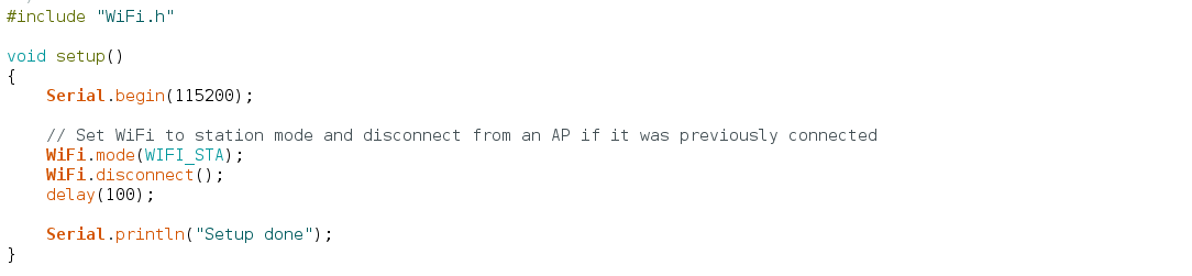
3. Open the following example under File > Examples > WiFi (ESP32) > WiFiScan
4. A new sketch opens in your Arduino IDE
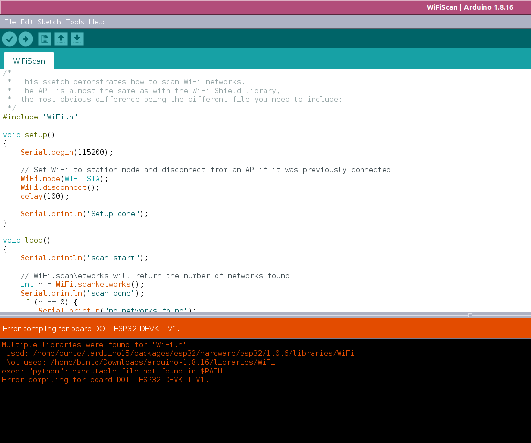
5. Press the Upload button in the Arduino IDE. Wait a few seconds while the code compiles and uploads to your board.
I´ve got the message:
exec: „python“: executable file not found in $PATH
apt install python-is-python3 python3-serial
Then i had to read: Permission denied: ‚/dev/ttyUSB0‘
vi /etc/udev/rules.d/01-ttyusb.rules
add: SUBSYSTEMS==“usb-serial“, TAG+=“uaccess“
udevadm control –reload
replug the ESP and now we are runnin.
open Tools -> Serial Monitor and set to 9600 baud and the magic happens 🙂

Goto Tools -> Manage Libraries and install:
MH-Z19
Adafruit_SSD1306
Adafruit_BMP280_Library
Adafruit GFX Library
Adafruit NeoPixel
AutoConnect
Calibration:
Connect module’s HD pin to low level(0V), lasting for 7 seconds at least.
Push the Button for 7 seconds at least.
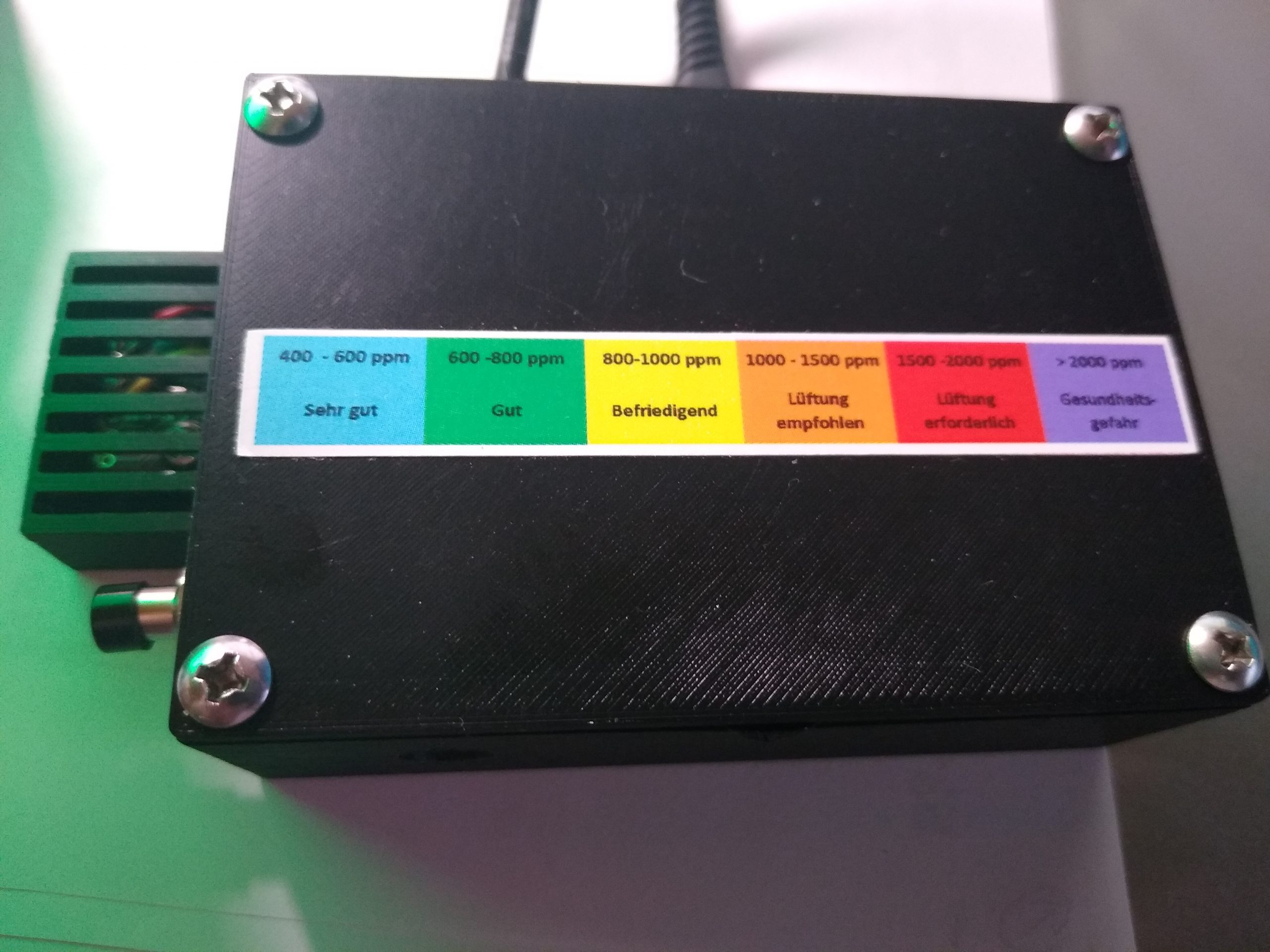
Before calibrating the zero point, please ensure that the sensor is stable for more than 20 minutes at 400ppm ambient environment.
Schaltplan
Sensors:
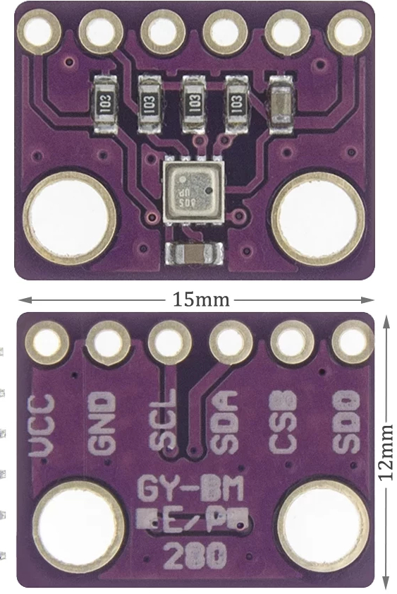
BMP280
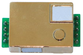
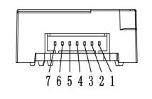
MH-Z19
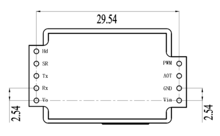
| Pin | Function |
| 1 | HD |
| 2 | Analog Output Vo |
| 3 | Negative Pole(GND) |
| 4 | Positive Pole(Vin) |
| 5 | UART(RXD)TTL Level data input |
| 6 | UART(TXD)TTL Level data output |
| 7 | PWM |
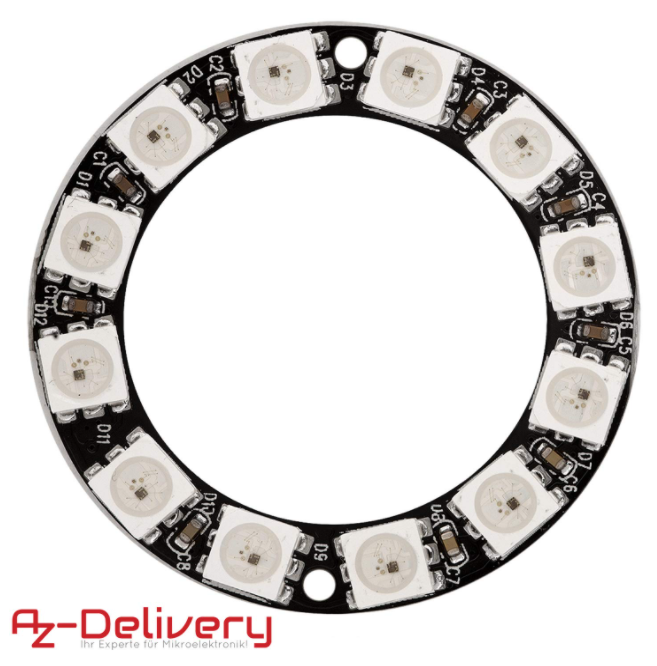
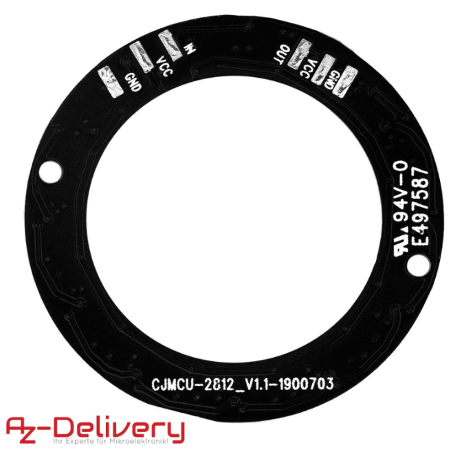
AZDelivery 5V RGB LED Ring WS2812B
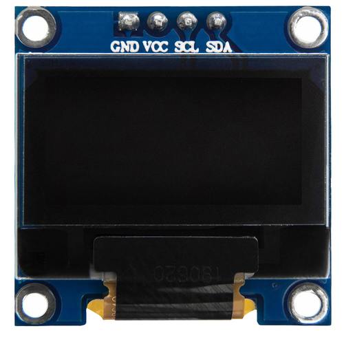
AZDelivery 0,96 Zoll OLED Display I2C
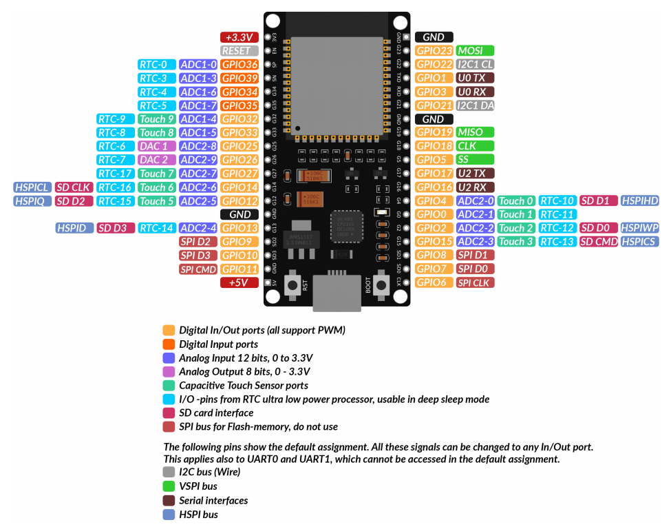
Board:
ESP-32 Dev Kit C V2
Sketches
Sketch (click to download) – CO2-Ampel-NodeMCU-Wroom-Mh-Z19-Oled-LED-BMP280-NoWeb
Sketch (click to download) – CO2-Ampel-NodeMCU-Wroom-Mh-Z19-Oled-LED-BMP280-WebAutoConnect
After connected you can destroy the configuration with /_ac
Einiges übernommer von https://unsinnsbasis.de/.